Ever since the record-breaking STAC T0 benchmark was published, we've been getting a number of similar questions from prospective customers. In response, we will be publishing a series of articles describing the LDA ultra-low latency IP framework in detail, which will also include answers to the most common questions.
The first in the series, this article covers the networking inside and outside the server that hosts the FPGA board running the IP framework.
LDA Framework: Network Setup
Lightspeed v2 TCP offload engine is a hardware-assisted TCP/IP stack based on Solarflare's (now Xilinx) Onload® technology. A regular BSD socket-compatible programming model is used to create, destroy and actively maintain the TCP session in software, while the FPGA is only responsible for sending latency-critical TCP packets. This approach allows the creation of a "no-compromise" solution that takes the best from both worlds. Software session management is familiar and feature-rich, while FPGA-assisted TCP payload transmission is ultra-fast and extremely low-latency. An Onload-compatible network adapter is also present in the system, so FPGA-accelerated and software strategies may work in parallel, significantly reducing the development and infrastructure costs.
Below we discuss the most popular deployment models.
The Basic
This is the first, basic framework setup that was first introduced in 2017, when the first version of LDA's TOE was introduced and subsequently benchmarked by STAC in the first ever T0 test.
The setup is simple but extremely versatile and has been widely adopted by LDA's customers around the world.
The diagram speaks for itself; just a few notes before moving forward:
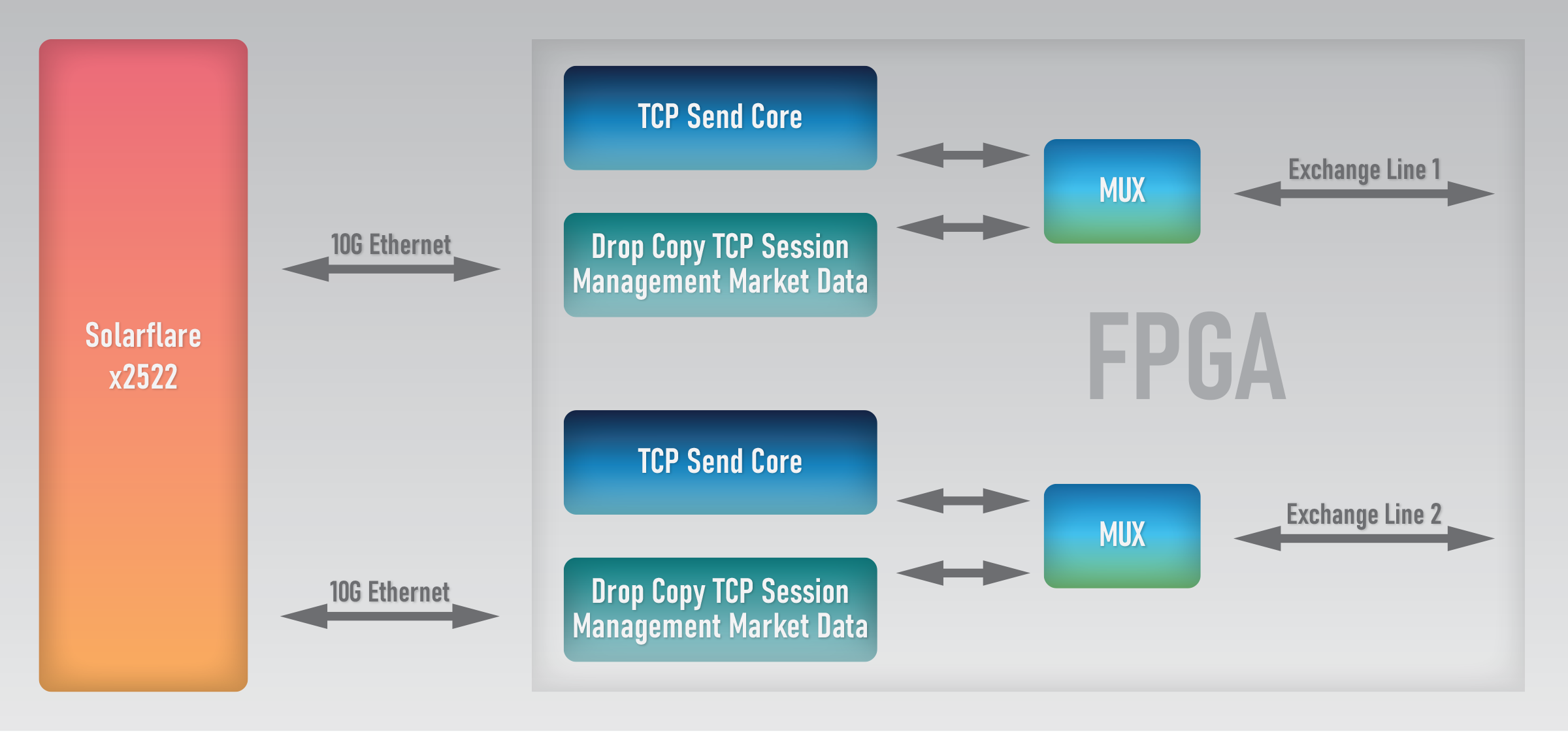
- The model builds on existing software setups that have been deployed by the firms for years. Many companies deployed thousands of dual-port Solarflare network adapters - from 7000 series to the newest 25G-capable x2522. Typical setup connected A and B side feeds coming from the exchanges, with one or both ports also responding to market data events with TCP messages.
- FPGAs plug into the existing infrastructure perfectly. The lines going to the exchange are connected to the FPGA; with both ports on the NIC becoming daisy chain connections. The FPGA is transparent to the software applications; they continue working with the NIC as before.
- Data mux in the FPGA is not overly complex and does not introduce any additional latency for the FPGA code. Of course, it does require smart data management, which is a part of LDA's framework and is fully transparent to the applications. No need to get into details, just a hint: the NIC is not sending latency-critical data, so all the time in the world is available to get the data sent.
- There is the possibility to use just one port on the NIC to manage two, or even more ports going from the FPGA to the exchange. This makes data mux even more complex, so it is recommended to check the "latest and greatest" framework described in the last section.
The Simplest
The Simplest is a significantly simplified Basic setup. With the wide adoption of LDA's TCP offload engine and framework, we realized that many customers are using network muxes for their access to the exchange. Such devices, also featuring Layer 1 replication for the ingress data, allow sharing expensive exchange lines between multiple trading hosts albeit with a latency penalty, which is nevertheless much lower than regular Layer 2 switch.

A setup that includes such a device can be further simplified: the egress mux between FPGA logic and the NIC can be removed. Also, as an option, the daisy chain for the ingress data can be removed as well. The NIC's port has its dedicated wire to the mux device.
The most critical latency metric — FPGA to market latency — remains the same with this setup compared to the previous one. Hence, the most significant benefit of using this model is a simpler FPGA logic, which results in significantly faster builds. During the active R&D cycle, multiple builds are done per day; so, saving even 20 minutes per build adds up quickly to multiple man-days for a moderately complex project.
This model's limitations are also quite obvious: the company should own a mux device, and it should have enough free ports to connect the NIC and all the wires from the FPGA. This could already be too expensive on a hosted mux device, as many hosting companies are charging their customers on a per-port basis. Also, not all mux devices have per-port priority settings, which can become a problem when the application is also sending many messages from the software through the NIC. Unlike The Basic model, where an FPGA is doing smart arbitration and always prioritizes its own traffic, here we have to rely on the mux device itself. So, too many messages from the software may get in the way of latency-critical traffic from the FPGA.
This setup is useful in specific cases to significantly reduce development costs and improve time to market. It should be used with care.
The 100G
Despite the versatility and popularity of the basic deployment model, it has a few limitations. When we use more than two lines on the FPGA, or try to use a single port on the NIC to orchestrate multiple connections to the exchange, we always understand that there are theoretical use cases when the combined amount of daisy chain traffic may exceed 10G. In most cases, this doesn't happen: normally, the spikes on each individual line do not exceed 3Gbps, so even combining 2 or 3 lines is possible. However, on some options feeds, this model is not viable; also, we want to have as much safety margin as possible.
So, how to solve this? First of all, we could use the newest x2522 adapter in 25G mode. It improves the situation: combining multiple 10G lines into even a single 25G significantly improves the margin.
Another problem with The Basic setup is the need to keep MAC/PCS cores on the NIC side. Even though LDA's MAC cores are pretty small and efficient, they still consume logic cells and increase the build time. The solution to this problem is the FPGA TOE Framework - the best setup as of now. The framework uses 100G for communication between NIC and FPGA.
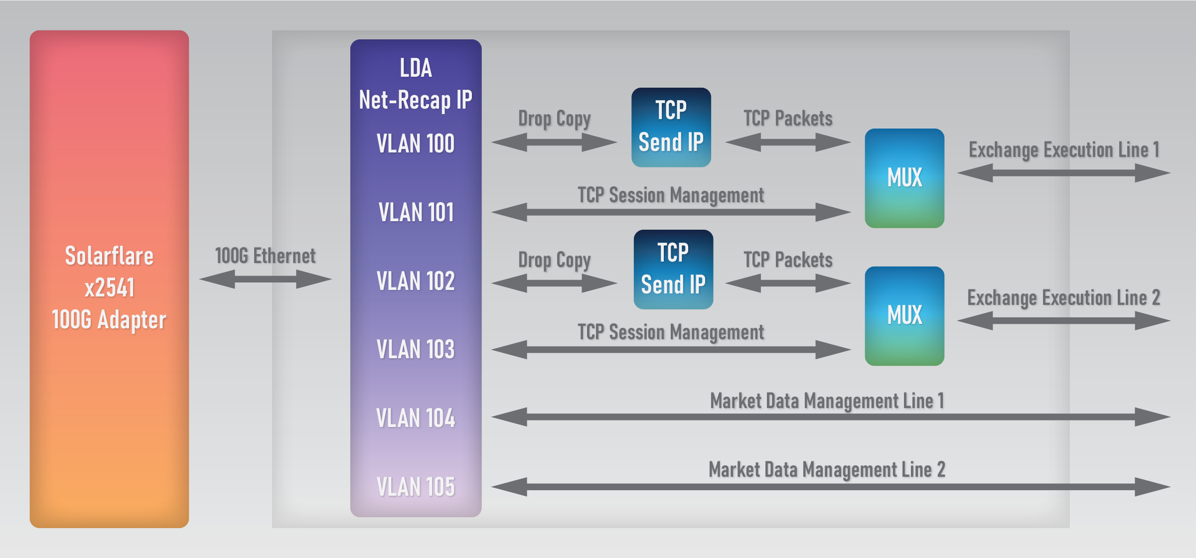
The NIC in this setup should be Solarflare (Xilinx) x2541. It has all the needed features, including Onload support, so using it becomes transparent to the application that was previously using Onload. A few facts about this model:
- Unlike 10G or 25G, the 100G MAC/PCS is a hard IP in all Virtex Ultrascale+ FPGAs. So, it consumes no logic cells.
- One 100G port can orchestrate up to ten 10G links connected to the FPGA without the risk of dropping packets. In reality the capacity is much higher, given that trading lines rarely reach 10G bandwidth for long periods of time. Thus, a single 100G link is enough to potentially manage all 4 QSFPs on the FPGA.
- VLAN tags are used to distinguish between the ingress and egress traffic on each exchange line. The framework includes parts of LDA's innovative NetRecap product to facilitate the process. Each line has its dedicated VLAN tag that software can use to send data to the exchange. The framework can also use "virtual VLANs" that deliver data to the user logic, instead of the physical Ethernet lines.
Let's review the last point in more detail, as it introduces a very interesting application design option. Typically, the software uses PCIe to configure and communicate with the FPGA IP. In simple cases, it is just registers access. In more complex cases, the FPGA implements PCIe DMA to move big chunks of data. The problem is that PCIe DMA uses a lot of space in the FPGA; this is especially true for PCIe x16. Besides longer builds, the PCIe DMA logic must reside in specific areas of the chip, potentially getting in the way of critical IP and increasing its latency.
So, why don't we use 100G Ethernet instead? Indeed, there are pretty compelling reasons to at least consider this non-standard approach:
- 100G adapters implement a very efficient PCIe x16 state machine since they have to move a lot of data very quickly. So, we can easily bet that the PCIe transfer will most probably be faster than the one implemented directly by an FPGA. There already are adapters implementing the PCIe 4.0 standard, and their number will be increasing.
- Sending the data from the application becomes much more straightforward using the regular Berkeley socket API. The Solarflare (Xilinx) x2541 implements all Onload features, including ef_vi so that the application can use the whole bandwidth without any protocol overhead.
- Of course, there is a latency penalty on a100G connection between the adapter and FPGA. However, 100G adapters are made to be very efficient, and the 100G MAC/PCS core present in the Virtex Ultrascale+ FPGA has surprisingly low latency. So, total end-to-end latency might be slightly higher than that of direct PCIe transfer to FPGA, but will still be significantly lower than 1 microsecond per transfer. High-bandwidth transfer scenarios may prove to be faster since implementing PCIe x16 on FPGA is not always convenient.
- Handling code on the FPGA is also much simpler, with less overhead.
Sacrificing a QSFP port?
One consideration against using the 100G model is that one whole QSFP port on the FPGA board is "sacrificed" for the daisy chain connection. This is a limitation, of course, especially on boards that feature one QSFP or for boards with two QSFP ports if more than four 10G lines are needed for exchange connectivity. However, many FPGA boards feature 4 QSFP ports; in which case, the limitation is not critical.
There is a better way, though. LDA's SBM09P-3 FPGA board is made with this setup in mind: it features an additional Firefly connector specifically for daisy-chaining a 100G NIC. So, all four QSFPs are available for the user's application!